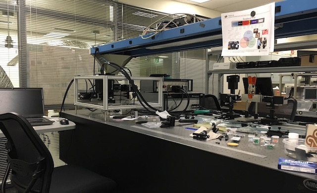
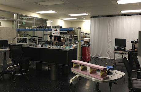
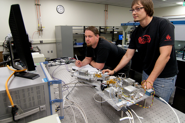
The NEAR-Lab includes a 800 square foot lab space equipped with two independent Terahertz (THz) measurement systems. A variety of THz imaging experiments can be conducted using the three optical workbenches, THz focusing lenses, polarizers, and other optical components. Some of the equipment and capabilities present in the lab include:
The THz lab is located in room 60-06 of the Fourth Avenue Building (FAB) at 1900 SW 4th Ave, Portland OR 97201.
Terahertz (THz) radiation is a portion of the electromagnetic spectrum between 300 GHz (300 x 10^9 Hz) and 30 THz (30 x 10^12 Hz). As with every other part of the spectrum, there are applications and challenges. Terahertz is known for its ability to pierce through many materials (such as clothing and packaging material) and also for showing unique spectral features in different chemicals (much like we see colors in visible light). This allows us to image someone that could potentially holding a weapon, or scan for dangerous chemicals or explosives. Millimeter waves, just below the THz region, are currently in a testing phase in airport screening environments.
The NEAR-Lab measurement facility at PSU is equipped with two terahertz systems; the Picometrix T-Ray 4000 time-domain spectroscopy system and a Rhode & Schwarz ZVA-40 vector network analyzer equipped with Virginia Diodes ZVA extender systems.
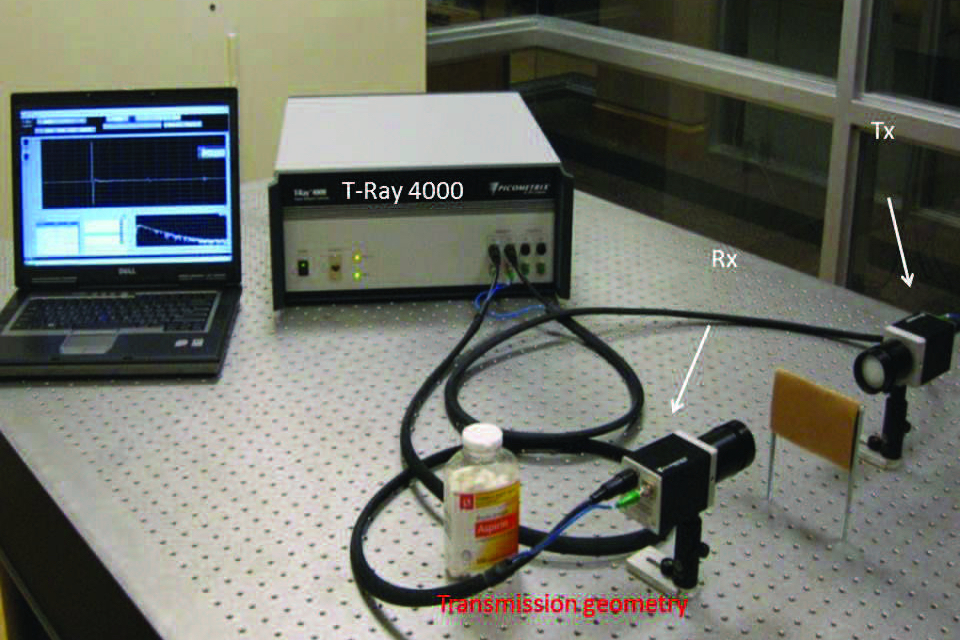
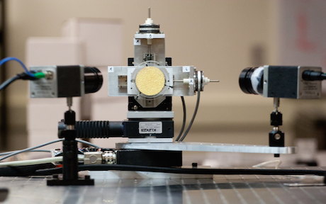
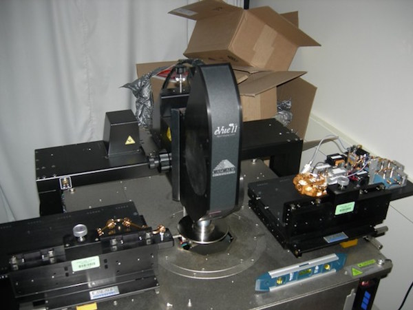
The Picometrix T-Ray 4000 (shown above), emits a short burst radiation, which is focused by a polyethylene lens into a collimated beam. The beam travels through air and is then detected and processed for frequency content. The system can be configured in reflection mode (beam scatters off object, shown on right) or transmission (transmits through material of interest, shown on left). Our reflection mode setup includes a motorized arm that automatically scans across angle with precision of 0.001 degrees. With one minute of averaging, the detected signal contains frequencies out to 4.0 THz.
System specifications:
• Laser frequency: 780-850 nm
• Detector time-resolution: 78 picoseconds
• SNR: 80 dB at 0.5 THz
• Labview-based operating system
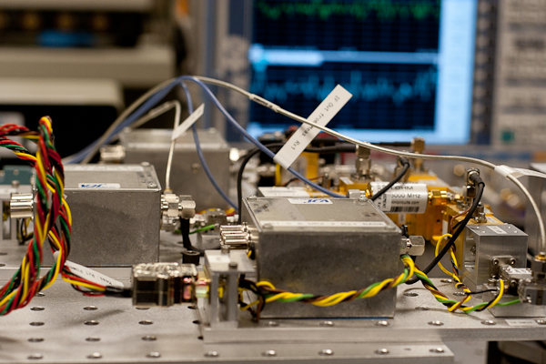
The Virginia Diodes ZVA extender systems operate by taking the 40 GHz signal from the Rhode & Schwartz VNA and running it though a modular series of frequency doublers, triplers, subharmonic mixers, and amplifiers. Six configurations are possible, allowing narrow band, continuous wave measurements that span 75 to 750 GHz.
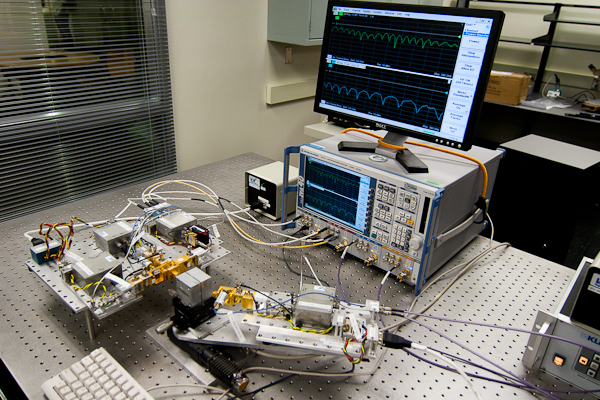
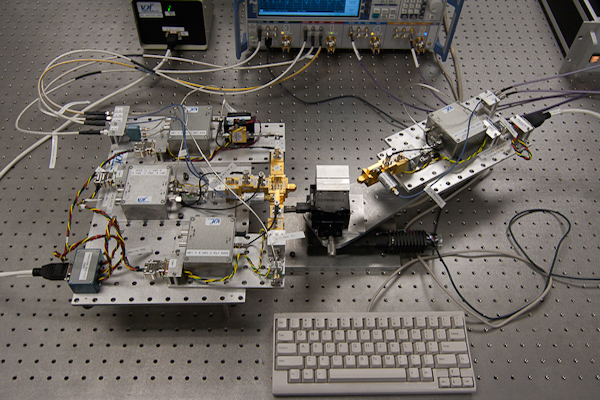
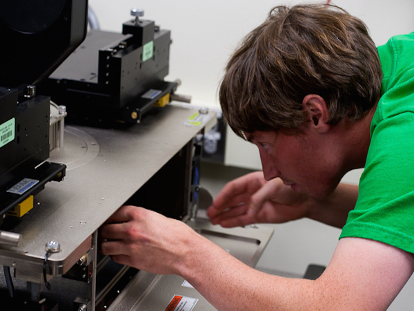
PSU is working in an collaborative effort with Cascade Microtech to build a probe station to characterize devices in the THz range. Shown below is the Cascade Microtech probe station to be equipped with the Virginia Diodes frequency extenders.
A collinear head can be mounted on an imaging gantry from Picometrix to raster scan samples.
The imaging system is capable of:
• Live streaming images
• x-y scan with full frequency spectrum
• 3-d tomography
• Scan resolution: 125 microns
Each pixel that is imaged will record a time domain waveform. Using the time of arrival of each pulse, an image would represent a contour of a surface. If that pulse was Fourier transformed with an appropriate color code, an image could be made according to some unique reflection spectra.
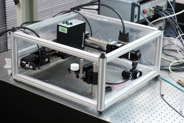
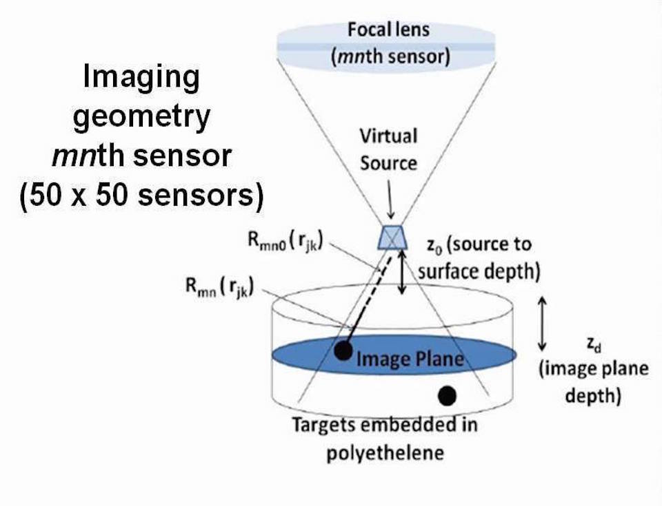
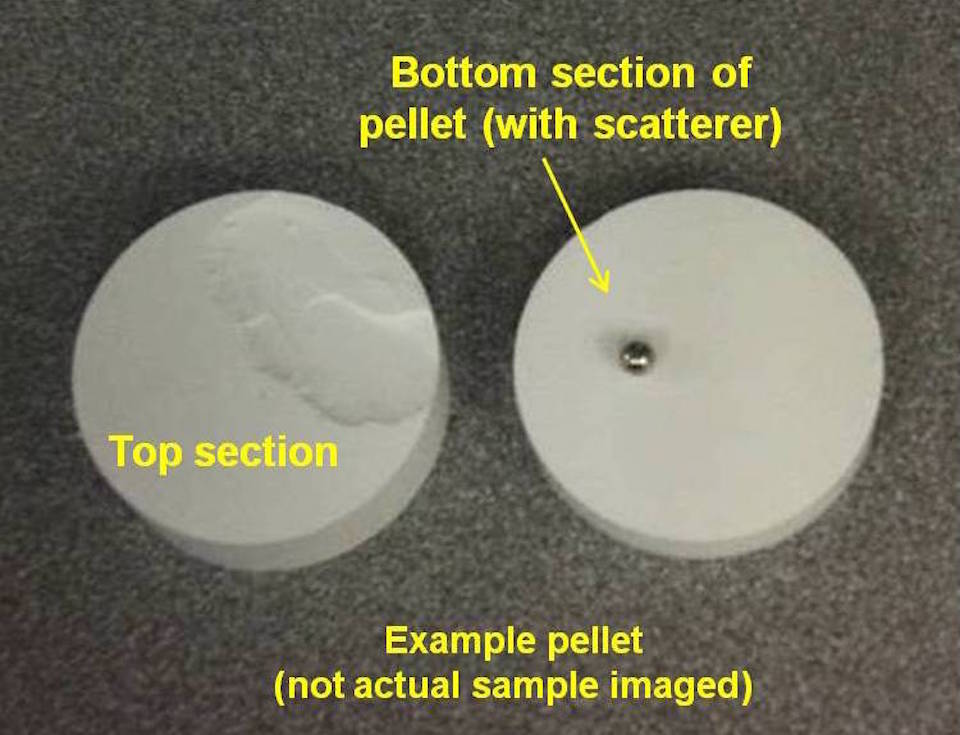
Another possibility for THz imaging is to utilize a synthetic array. In order to synthesize an array, the antenna beamwidth must be large. We achieve this by placing the object we want to image intentionally below the focal point of a focusing lens. The beam diverges below the focal point, thus multiple sensor locations will illuminate a single spot on the object. In practice, the transceiver is raster scanned back and forth with the object stationary. We record sensor data in a 2D grid and using post-processing we reconstruct the image in the focal plane of interest. This is particularly important with 3D objects that contain volume scatterers. One example of this imaging capability is the imaging of a polyethylene cylinder with two steel ball-bearings embedded inside. The figure below shows the measurement configuration and a sample prepared similar to the one being imaged.
Below two sequences of images are created at different synthetic focal depths. The depth is swept from the surface of the pellet to 2.3 cm deep. The ball-bearings are located at 5 mm and 12 mm below the surface. Two videos below show these sequences at 250 GHz and 500 GHz, respectively.